Stamp: Modular Breakout Boards for SMD Prototyping https://hackaday.com/2025/05/28/stamp-modular-breakout-boards-for-smd-prototyping/ #Stampbreakoutboards #kickstarter #Sciotronics #breadboard #hardware #PCBHacks

Stamp: Modular Breakout Boards for SMD Prototyping https://hackaday.com/2025/05/28/stamp-modular-breakout-boards-for-smd-prototyping/ #Stampbreakoutboards #kickstarter #Sciotronics #breadboard #hardware #PCBHacks
Stamp: Modular Breakout Boards for SMD Prototyping - [Kalesh Sasidharan] from Sciotronics wrote in to tell us about their project, Stam... - https://hackaday.com/2025/05/28/stamp-modular-breakout-boards-for-smd-prototyping/ #stampbreakoutboards #kickstarter #sciotronics #breadboard #hardware #pcbhacks
Mein mobiler Programmierplatz nimmt langsam Formen an.
Es fehlt noch ein #Labornetzgerät (schon im Hause) ein #Breadboard (bestellt) und ein #WlanRouter (bestellt), dann kann ich bei schönem Wetter auch auf dem #Balkon programmieren
Well made, intro about how breadboards work.
Enjoy!
https://mastodon.social/@GurgleApps/112275105851772055
I designed a #SMD adapter board using @kicad and let @aislerhq manufacture them. They are for #SOT23 on one side and #SOT363 on the other side. They bridge the gap of a #solderless #breadboard, so they are perfect for #prototyping circuits or trying out new components - or as replacement for through-hole parts. I soldered a dual diode #BAV70 on one and a dual NPN/PNP transistor #BC847BPN on a second one to try them out. I'm satisfied how they look, although the white area for labeling is a bit small - I need a thinner pen for that.
You can find the shared project here: https://aisler.net/p/UTAGNLYX (trying out this feature, please give feedback if you use it).
#diyelectronics #soldering #kicad #aisler
I wrote an instructions for a simple way to make a phono equalizer that converts the output signal of an MM cartridge to standard audio signal.
It was made using an universal board printed in the breadboard wiring pattern.
Please visit the following contents:
Google Translated:
https://bokunimo-net.translate.goog/blog/audio/5658/?_x_tr_sl=ja&_x_tr_tl=en
Original Site written in Japanese:
https://bokunimo.net/blog/audio/5658/
I'm planning another module for my #StackSynth - a #VCF based on the #LM13700 and the Skull & Circuits VCF-3: https://www.skullandcircuits.com/vcf-3/
I already designed the #PCB in #KiCad but wanted to test it on a solderless #breadboard first. It works fine, so I ordered the PCBs.
#diysynth #electronics #synthesizer
Print your own USB connector http://lucstechblog.blogspot.com/2025/03/print-your-own-usb-connector.html #3dprinting #breadboard #soldering
One of the final modules for my #StackSynth project: the #noise generator. It outputs white, blue, and pink noise and uses a #3904 and a #TL074 with a lot of resistors and a couple of capacitors.
It is based on Moritz Klein's video: https://youtu.be/0yB_h_wFkh4
I prototyped it on solderless #breadboard and then designed the #PCB in @kicad and let @aislerhq manufacture them again. It turned out quite nice and sounds great.
#soldering #diysynth #synthesizer #KiCad #pcblayout #MoritzKlein
My #Z80 machine is getting some new input devices.
Watch this space!
Finished #soldering. What I learned so far: l should clean between soldering #SMD components and #throughhole ones. I should leave enough space between the SMD components. I also dislike 0806 #resistors, better get some in 1206 size. The #capacitors were okay.
I tried it out with a square and a triangle wave as two inputs, connected through #potentiometers on a mini #breadboard and looked at the #oscilloscope
#diyelectronics #electronics #diysynth
Help.
I am going nuts.
I have a DC Power supply. I feed a PWM with that. I have two Mosfets, Drain and Source are in parallel with the PWM, but the gates:
1. Connected to Negative Terminal of the PWM. I can tune a LED (load) just fine (dim).
2. Connected to the Positive Terminal of the PWM. The LED lights constantly.
This should be the easiest thing in the book. Why is this failing? I even tried some pull-down R's (1k, 10k) to no avail.
My thought: Having a Pos-Gate Mosfet and a Neg-Gate Mosfet will turn one led up and the other down, and vice versa.
Safety advisory: Always discharge your capacitors. Especially for some breadboard testing.
Ask me how I know.
Ouch.
Starting making something today!
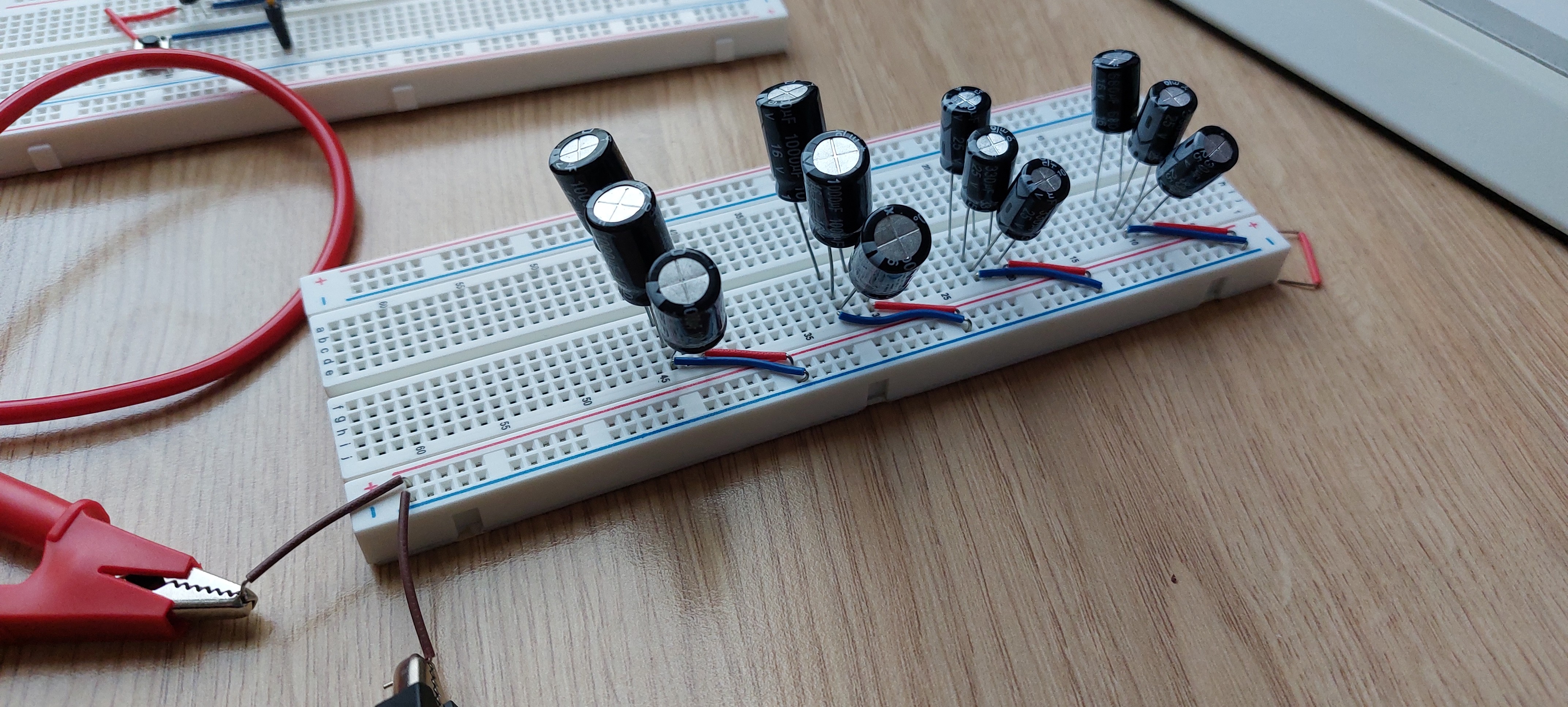
Try your hand at making The Ultimate DIY 3220-Point Breadboard - a project that will have you creating a breadboard equipped with its own three separate power supply capabilities: a 12VDC power jack, bench-top power supply hookup, and an onboard 9V battery supply.
This is a neat and handy project; one that's perfect for the individual who wants to make a serious electronics project at the beginner level.
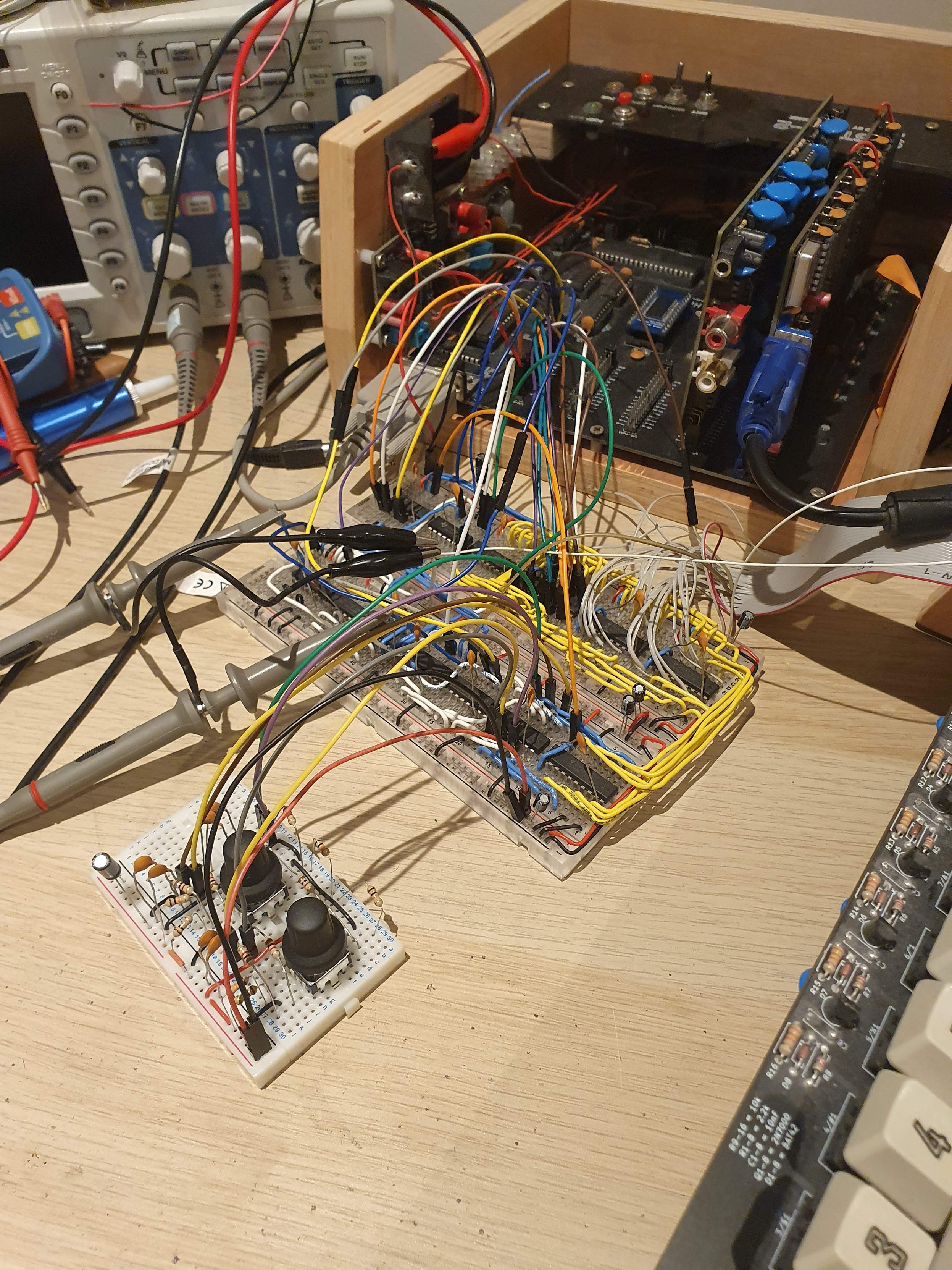
https://motbots.com/the-ultimate-diy-3220-point-breadboard/
can anyone tell me iof theres a specific name for the type of protoypying PCB thats in this picture, (the green one in bottom left) I've seen them refered to as gold finger PCB, but not sure. its to plug into cartridge port of dragon 32
I'm looking to get one in the UK so any suggestions where to get one a browse on amazon didnt get me much luck,but I may have been searching for the wrong thing
No Frills PCB Brings USB-C Power to the Breadboard https://hackaday.com/2025/01/06/no-frills-pcb-brings-usb-c-power-to-the-breadboard/ #powersupply #breadboard #ToolHacks #USBC
No Frills PCB Brings USB-C Power to the Breadboard - At this point, many of us have gone all-in on USB-C. It’s gotten to the point that... - https://hackaday.com/2025/01/06/no-frills-pcb-brings-usb-c-power-to-the-breadboard/ #powersupply #breadboard #toolhacks #usbc